Inside a Bourdon Pressure Gauge: How the Movement Works
Follow pressure through the Bourdon tube and mechanical movement to the pointer, using the AccessRA Movement A model while keeping gauge-design differences explicit.
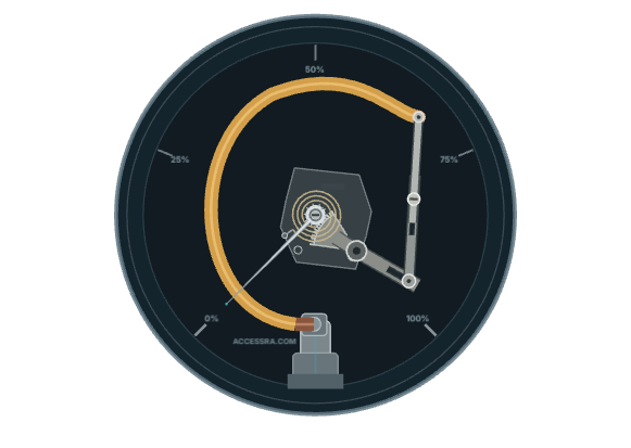
The Bourdon tube is the sensing element
Internal OperationPressure enters the gauge through the socket and acts inside the Bourdon tube. In a common C-shaped Bourdon element, increasing pressure causes the tube to change shape slightly and the free end to move. The movement is small, so the gauge mechanism must transfer and amplify it into useful pointer rotation.
Bourdon elements are not all the same shape; depending on range and model, manufacturers also use helical or other constructions.
Try it: follow Movement A
Validation / ProofSelect the Bourdon tube, free end, link, sector, pinion, hairspring and pointer. Apply pressure while keeping the same movement on screen. The demonstration is the AccessRA Movement A training geometry, not a universal internal layout.
From tube travel to pointer rotation
Internal OperationThe free-end displacement is transferred by the link to the toothed sector. The sector drives the pinion/spindle, which rotates the pointer across the dial. In the AccessRA model, the hairspring maintains light preload in the gear train to help control backlash; it is not the pressure-sensing element.
This mechanical chain is why friction, link geometry and gear condition can affect indication even when the Bourdon tube itself is responding to pressure.
Why identifying the movement matters
Field NoteTwo gauges can have similar dials but different internal adjustment arrangements. Some movements provide separate zero/span/linearity provisions; others do not. Identify the gauge and movement before applying any adjustment method or direction.
Continue learning
Technical basis, limitations & references
Applicability
Mechanical Bourdon-tube dial pressure gauges. Diagnostic patterns such as zero, span, linearity, hysteresis and friction are discussed as measurement behaviours. Where an adjustment is shown, the direction and geometry apply only to the identified AccessRA Movement A training model unless an OEM reference is named.
Limitations
Do not treat the simulator values, adjustment direction or tolerance example as a universal manufacturer procedure. Actual acceptance limits and adjustment provisions depend on the gauge design, applicable standard, OEM documentation and site procedure.
Safety boundary
Use pressure-rated reference equipment, hoses, fittings and test media compatible with the gauge. Do not exceed equipment ratings. Isolate and fully depressurise the setup before breaking any pressure connection.
Validation basis
Simulation-backed. Simulation-backed AccessRA training content cross-checked against cited OEM/metrology references. The focused article demonstrations reuse the same fault-pattern and Movement A rendering logic used by the AccessRA Gauge Test Lab. The simulations illustrate diagnostic behaviour; they are not a substitute for an OEM-specific repair instruction.
Document control
Revision R1 · Technical review Approved · Evidence review Evidence Approved.
References
WIKA Handbook — Pressure & Temperature Measurement
WIKA · Pressure measurement handbook
Open reference ↗
Pressure Gauge Installation and Maintenance Instructions
Ashcroft · Pressure gauge calibration/maintenance manual
Open reference ↗
AccessRA Gauge Test Lab — Technical Baseline
AccessRA · Gauge Test Lab baseline